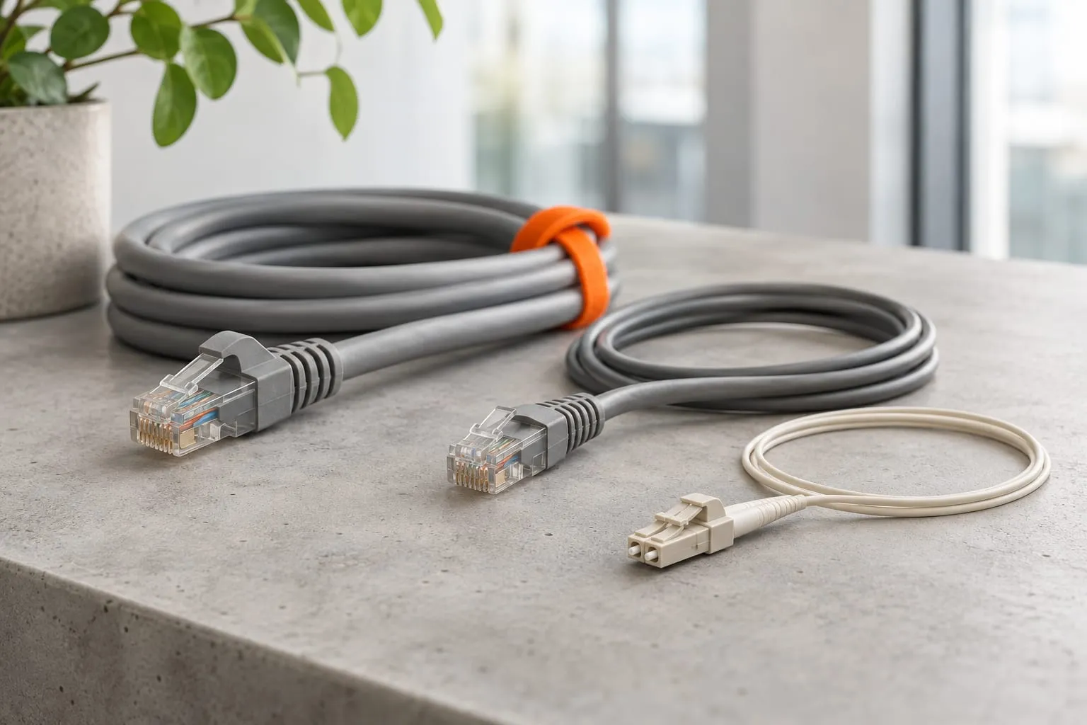
Which cable belongs at a desk and which belongs in the backbone?
Use copper where a short office link needs convenient Ethernet and possibly power; use fiber where distance, aggregation or electrical isolation favors an optical connection. Most designs will mix the two. There is little value in choosing one cable type for every route regardless of its job.
Desk outlets, phones, cameras and wireless access points often use twisted-pair copper. Twisted pairs are insulated conductors arranged to help control interference. Fiber carries light through glass and is commonly used between network cabinets, floors or buildings.
A backbone is the link that carries traffic between parts of the network, such as an access switch and the central switching equipment. It may aggregate traffic from many endpoints, so its capacity requirement differs from that of a single desk. Mark those roles on the drawing first. A desk outlet and a link carrying a floor of traffic should not start with the same capacity assumption.
Our networking solutions service checks the cable routes alongside switch ports and the devices they serve. Buy the cable after that work, when you know what each link must carry.
What speeds and distances distinguish Cat6 from Cat6A?
Cat6 can support 10GBASE-T over distances up to about 55 meters under suitable installation conditions; Cat6A supports 10 Gbps channels to 100 meters. Treat those as application limits. Test the installed link before relying on it for the chosen speed.
10GBASE-T is an Ethernet application that carries 10 gigabits per second over twisted-pair copper. Cat6 and Cat6A are cabling performance categories, not promises that every connected device will operate at that speed. Check the equipment at both ends too. A cable category cannot make a gigabit port run at 10 Gbps.
| Link choice | Typical role | Distance and application consideration | Power consideration |
|---|---|---|---|
| Cat6 | Desks and shorter copper links | Gigabit Ethernet to 100 m; 10GBASE-T up to about 55 m subject to conditions | Can carry PoE with suitable components and design |
| Cat6A | Copper links planned for 10 Gbps | 10GBASE-T channel to 100 m within the applicable specification | Evaluate PoE load, bundles and temperature |
| Multimode fiber | Cabinet and shorter backbone links | Reach depends on fiber grade and optical application | Does not carry PoE |
| Single-mode fiber | Longer backbones and inter-building links | Reach depends on transceivers and the optical budget | Requires power at remote equipment |
The 100-meter copper channel allowance includes patch cords, not just the cable hidden above the ceiling. A conventional structured cabling design reserves part of that distance for cords and connections. Check the applicable channel model and component specifications instead of using the entire allowance for the fixed run.
The shorter Cat6 10GBASE-T reach is sensitive to alien crosstalk, meaning interference arriving from nearby cables. For existing Cat6, assess the installed link for 10GBASE-T before approving it. The writing on the jacket is not a test result.
When should single-mode or multimode fiber be selected?
Select fiber using the planned Ethernet speed, route distance and matching optical interfaces. Single-mode is often appropriate for long routes, while multimode can suit shorter internal backbones when its supported reach meets the design.
Single-mode and multimode describe different ways light travels through the fiber core. They use different optical arrangements and are not interchangeable merely because connectors look alike. Multimode grades also differ in supported performance.
Specify the complete link: switch interface, transceiver, fiber type, connectors and required reach. The optical budget compares transmitted light and receiver requirements against losses through the cable and connections. A short route can still fail that check. Extra connectors add loss, as do poor splices and dirty end faces.
Between buildings, fiber avoids an electrically conductive data path, which can help address differences in electrical potential. The route still needs appropriate protection and a review of building entry requirements. Metallic armor and other conductive components may introduce their own bonding considerations.
Plan spare fibers and accessible termination space where future changes justify them. If a route will be difficult to reopen, the installation work is a good time to add spare strands. Tie the quantity to a written expansion plan rather than ordering extras without a purpose.
How do PoE and cable heat affect the design?
Power over Ethernet, or PoE, supplies electrical power over copper data cabling, and its current creates heat. Select cable, connectors and installation arrangements for the actual endpoint power requirements and ambient conditions.
An access point or camera needs a suitable switch power standard and enough available power from the switch budget. Check the whole switch, not one port. A per-port power rating does not mean every port can deliver it at once. Check total loading and behavior during startup.
Cable bundles can retain heat, especially in warm ceiling spaces or crowded containment. Conductor size, cable construction, bundle arrangement and temperature ratings matter. Check the cabling guidance and product limits. Moving up a category does not by itself settle the heat calculation.
Avoid copper-clad aluminum products for standards-based structured copper cabling. Specify suitable solid-copper conductors and compliant connecting hardware, then verify the supplied products. Ask for the conductor material in the quotation. Network cable is too vague a description to buy against.
Fiber cannot power a remote access point or camera. A fiber-fed location therefore needs local power, or a separately designed power arrangement, plus equipment to convert the optical link into the endpoint connection. Include that equipment and its backup power in the design.
What do Wi-Fi 6, Wi-Fi 6E and Wi-Fi 7 change?
Newer wireless generations can increase the capacity required at an access point’s wired uplink, but the access point model determines the port and power requirements. Do not order the cable or switch from the Wi-Fi label alone. Read the access point datasheet.
Check whether the proposed access point has a gigabit, multigigabit or 10-gigabit interface. Multigigabit Ethernet includes rates between ordinary gigabit and 10-gigabit operation. Match the intended rate to the supported cabling application and installed distance.
The advertised radio capacity is not the same as sustained traffic crossing one wired port. Client capabilities, channel planning and simultaneous use affect real traffic. Still, a difficult ceiling route may justify Cat6A when the plan anticipates later access points with higher uplink requirements.
Put access point outlets where the wireless design needs them, rather than where a desk cable happens to end. Record mounting position, outlet identity and switch port power requirements. Location comes first here. More uplink bandwidth cannot fix a coverage gap caused by putting the access point at the wrong outlet.
Does shielding make every copper installation better?
Shielding helps control interference only when the complete system is selected and installed correctly. It also needs compatible components and correct bonding. Choose it because the route warrants it.
Cat6A can be supplied in shielded or unshielded constructions. These are separate properties: Cat6A does not automatically mean shielded cable. Industrial equipment, crowded routes and separation from power circuits should be assessed during the survey.
Maintain the required separation from electrical services and follow local installation rules. Shielding is not permission to ignore routing guidance. Where the interference environment is difficult, fiber may be the clearer choice for the affected link.
Cable diameter and stiffness also affect installation. Confirm containment fill, bend radius and termination space before substituting a larger cable. The outlet may look fine after a bad pull. Excessive force, a crushed jacket or a tight bend can damage performance farther along the route.
Which cost drivers and acceptance tests should a buyer compare?
Compare the installed, documented link rather than the cable reel price. Route access, containment, termination quality and testing often determine how much disruption and rework the project creates.
Include labor for ceiling access, fire stopping, labeling and removal of abandoned cable where required. Fiber proposals should identify termination methods, patch panels and optical interfaces. Copper proposals should include outlets, patch panels, patch cords and the required certification tests.
Continuity is only the first check. It confirms basic conductor connections but cannot certify category performance. Copper certification tests the installed link against selected performance limits using suitable equipment and adapters. Specify the test standard, permanent-link or channel scope, and delivery of individual results tied to outlet labels.
For fiber, define inspection, loss testing and any additional diagnostic tests appropriate to the route. An optical time-domain reflectometer can help locate events along a fiber, but it does not replace every acceptance measurement. Agree the method and pass limits before installation. Handover is too late to discover that the quote covered a different test.
What should the final cabling decision checklist include?
The final decision should assign a cable and test requirement to each link type. Keep the reasoning with the drawings. The next installer should be able to see why one route uses Cat6A and another uses fiber.
- Map endpoints, cabinet locations and measured routes, including patching allowances.
- Record required Ethernet rates and PoE demand for current and planned devices.
- Select Cat6 or Cat6A for suitable copper links and fiber for the required backbone roles.
- Match fiber types and transceivers, and review environmental and power constraints.
- Specify components, route protection, labels and acceptance test limits.
- Collect test files, outlet schedules, rack layouts and final route drawings at handover.
Use network installation planning to coordinate these decisions before fit-out work closes the routes. Share your floor plan and endpoint list through the contact form so we can check the routes against current use and the additions you expect.